>

Overview

Introduction
Film
Workspace

Reframed
Ambition

Masterpiece

Highlights

300,000 sq ft

offices on the river

80%

Of existing structure retained

50,000 sq ft

Terrace space

NABERS 5 *

DESIGN REVIEWED TARGET RATING

6 STATIONS

WITHIN A 10 MIN WALK

Renewably sourced

energy in operation

Location

Aerial
Transport
Wider area
Local area
Culture

WELL
CONNECTED

  • 6 stations within a 10 min walk
  • Waterloo is London’s busiest commuter station
  • Charing Cross and Blackfriars both within 10 mins walk
  • Direct access to The West End, City and Canary Wharf
  • Direct access to highly skilled workforce of SW London and Southern England
  • Direct access to all of London’s main rail terminals
ADDITIONAL TRAVEL TIMES
Clapham Junction 8 min
King’s Cross St Pancras 11 min
Heathrow Airport 36 min
Gatwick Airport 42 min
THAMES CLIPPER TRAVEL TIMES
Embankment – London Eye 6 mins
Embankment – Battersea Power Station 18 mins
Embankment – Tower Pier 19 mins
Embankment – Canary Wharf 30 mins

THE HEART
OF LONDON

76 Southbank is perfectly placed, close to some of London’s most popular districts. Covent Garden, Westminster, Soho, Blackfriars and The City are nearby, easily accessed by Tube or bike.

South bank
Parks
Landmarks
Cycle super highway

AN INSPIRING,
ENJOYABLE
NEIGHBOURHOOD

76 Southbank is just a stone’s throw from outstanding restaurants and bars, while peaceful parks, exceptional retail and world-renowned cultural venues are a short stroll along the riverside.

Bar and restaurants

1 Southbank Market
2 Queen Elizabeth Rooftop Garden
3 BFI Bar & Restaurant
4 House Restaurant
5 Honest Burgers
6 Ping Pong
7 The BBQ Club
8 Wahaca
9 Wagamama
10 Las Iguanas
11 Giraffe
12 The Understudy
13 KERB
14 The Green Room
15 Brasserie Blanc
16 Gabriels Wharf
17 Bar Elba
18 Black Sheep Coffee
19 Lyaness
20 12th Knot
21 Art Yard
22 Seabird
23 Benugo Waterloo
24 Leon
25 Island Poke
26 Wahaca
27 Waitrose
28 Hoxton Hotel
29 Gail's, Stamford Street
30 Tian Tian Market
31 Nando's
32 Paradise Burger
33 Gourmet Pizza
34 Black Sheep Coffee and Cocktails
35 Skylon
36 Benugo Southbank
37 OXO
38 Sea Containers
39 Konditor
40 The Kings Arms
41 Rosa's Thai
42 Gail's, Waterloo
43 Olivelli
44 Meson Don Felipe
45 The Anchor & Hope
46 Flat Iron

CULTURE & LEISURE

1 Hayward Gallery
2 Southbank Centre
3 BFI
4 National Theatre
5 Old Vic Theatre
6 Young vic theatre
7 1 Rebel southbank
8 Boom Cycle waterloo
9 Pure gym waterloo
10 London eye
11 Savoy Hotel
12 Central School of Ballet
13 The Violin Factory
14 The London Dungeon
15 Sealife
A unique

South Bank is home to original
thinking and cultural diversity – a
thriving mix of influences and energy.

Cultural hub

NATIONAL THEATRE

Southbank Centre

The Old Vic Theatre

THE NATIONAL THEATRE

OUTDOOR DINING ON THE QUEENS WALK, SOUTH BANK

TURBINE HALL, TATE MODERN

BLAVATNIK BUILDING, THE TATE MODERN

CHILDREN PLAYING OUTSIDE THE TATE MODERN

LONDON EYE

Food trucks on the Queen's walk

DANCER ON STAGE THE LONDON EYE

BLAVATNIK BUILDING, THE TATE MODERN

Building

Schedule of areas
Reception
Terraces
Summary specification

Schedule of areas

Floor
NIA SQ
FT
Terrace
SQ FT
Plan
Fifth floor
LET
Fourth floor
23,000
5,060
Third floor
LET
Second floor
LET
First floor
LET
Ground floor
44,733
Reception
10,560
1,690
Total
available
67,773
5,060
Fifth floor
Fourth floor
Third floor
Second floor
First floor
Ground floor
Reception
Floor plan
360
Images
Floor plan
Floor plan
Floor plan
Space plans
Floor plan
Floor plan
Space plan
Floor plan
Space plans
CGI

London’s
biggest
welcome

A spectacular double height entrance lobby welcomes you at ground floor level. The centrepiece staircase and transparent vertical core adds to the breathtaking scale of the 10,000 sq ft reception, making an unforgettable first impression.

> Open Floor plan
> Open Floor plan
> Open Floor plan

Space to
breathe

The building offers scale, while the horizontal
proportions allow for 50,000 sq ft of
outdoor terraces with stunning views
over the river and biophilic landscaping.

50,000 sq ft of private terraces

Unrivalled river views

Typically 6-8m deep

Highly useable space

BUILT

FOR

PURPOSE

10,000 SQ FT
RECEPTION

with 6m floor-to-
ceiling height

RECEPTION
CAFE

50,000 SQ FT
TERRACE SPACE

RENEWABLY SOURCED
ENERGY IN OPERATION

1:8 OCCUPATIONAL
DENSITY

Dual diverse-
located incoming
telecoms

14 l/s fresh air
per person per 8
sq m

2.9-3.2M
floor-to-ceiling
height

All electric
building

Four pipe fan coil
air conditioning

530 BICYCLE SPACES
AND LOCKERS

53 SHOWERS

FEATURE CENTRAL
ACCOMMODATION stair

Of existing
structure
retained

Unit protected
power provision

Standby generator

Targetting
WiredScore
Platinum

5 × 21 person
passenger lifts

and 2 x goods lifts

SERVED BY AIR
SOURCE HEAT PUMPS

ESG

Overview
Social
Pioneering

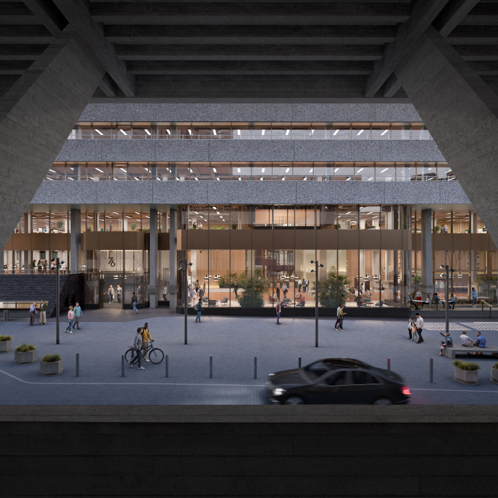
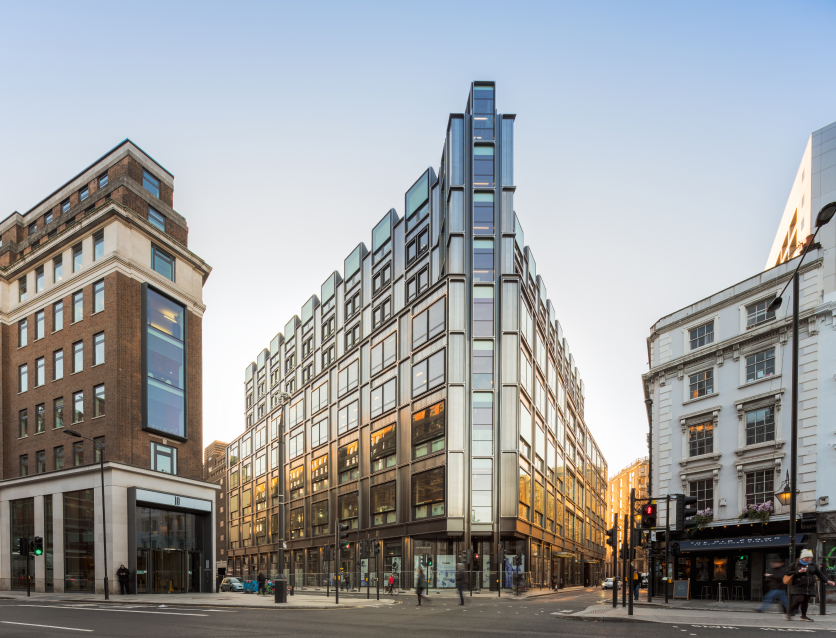
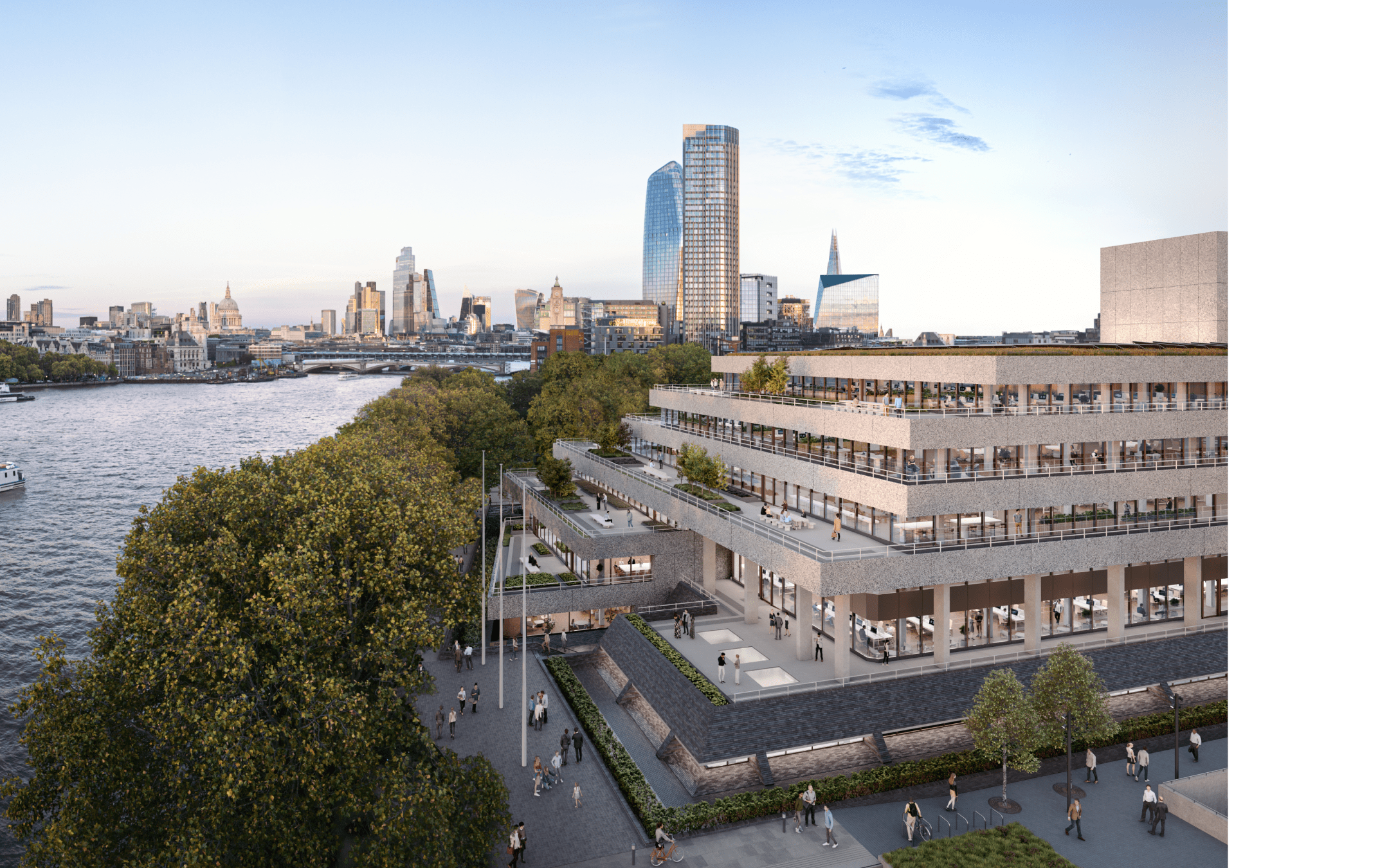
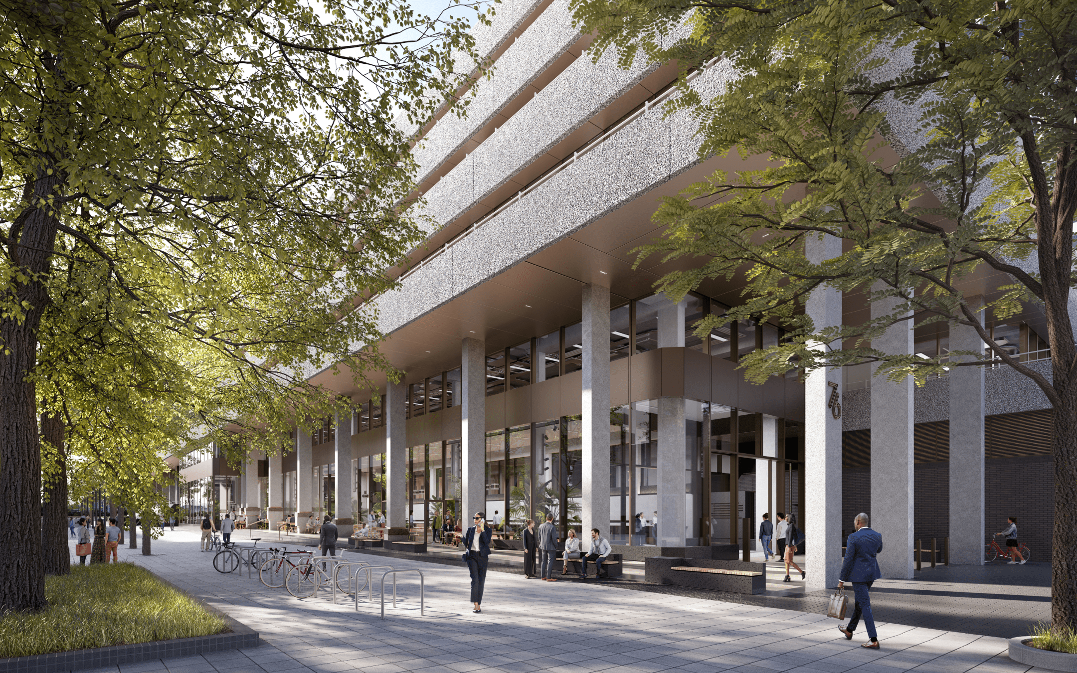
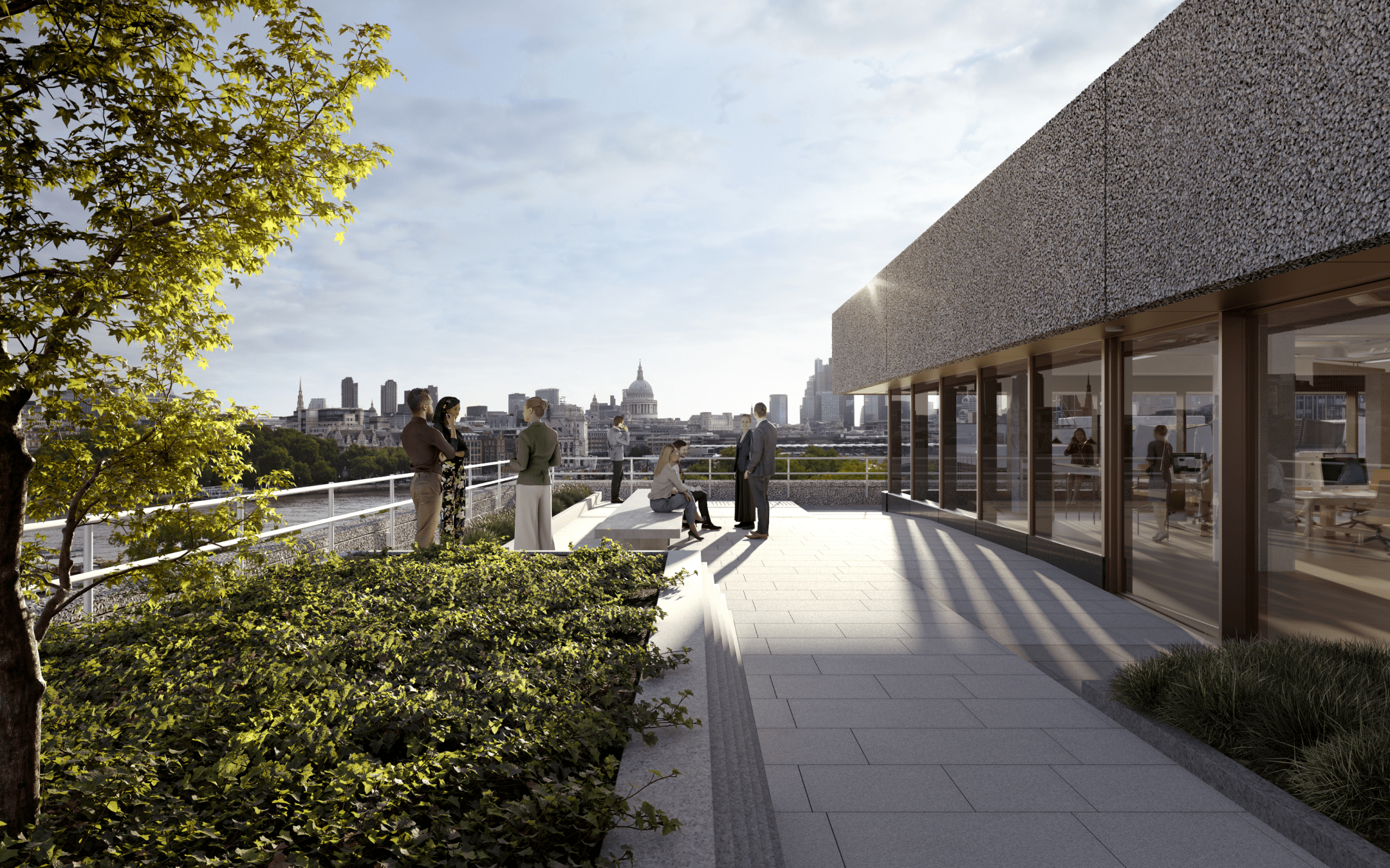
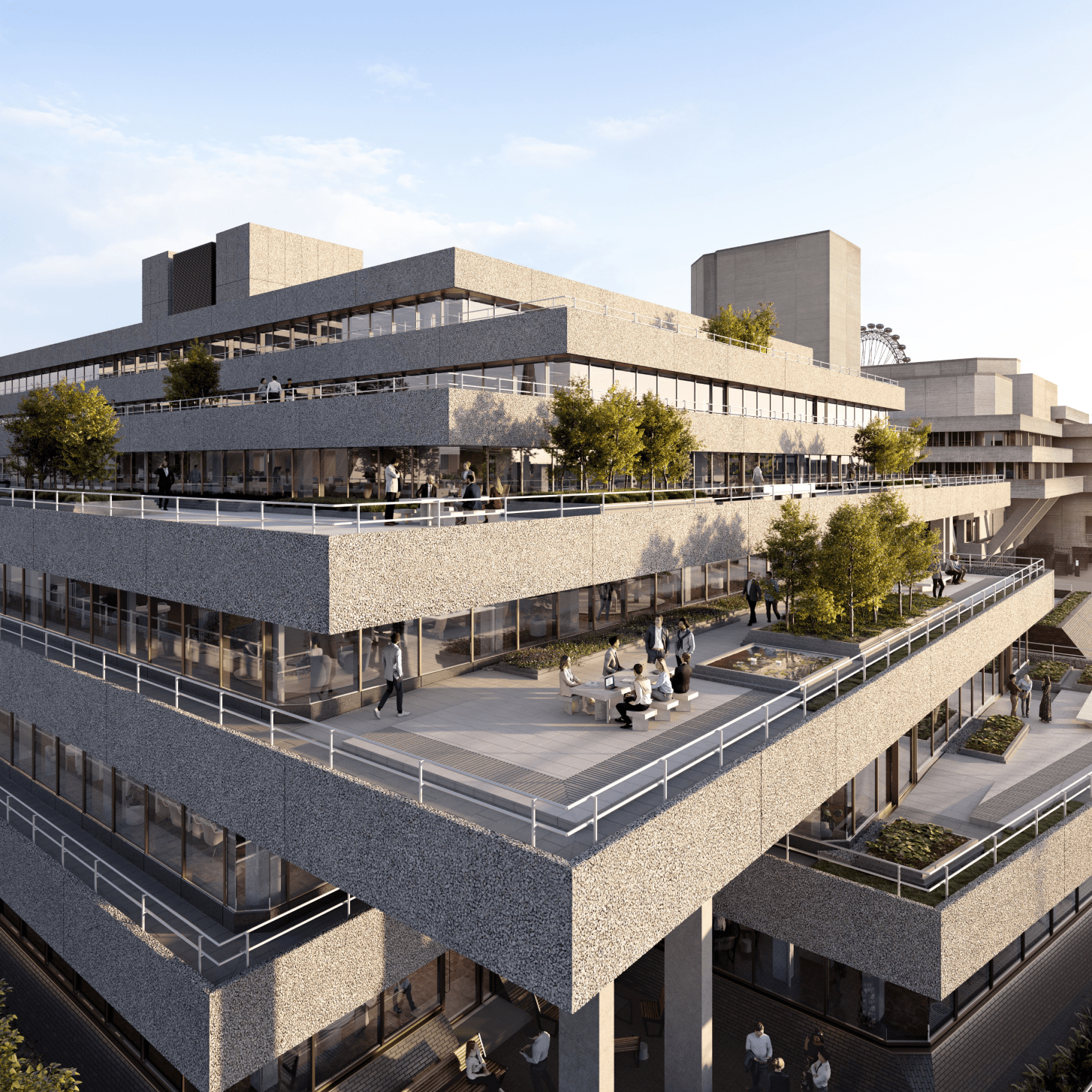
76 Southbank is an all-electric building
targeting a 5* NABERS rating, powered
from air-source heat pumps and a biosolar rooftop.
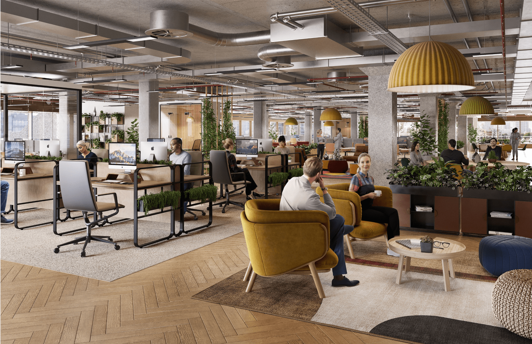
with purpose

BREEAM OUTSTANDING
(TARGETING)

NABERS DESIGN
Reviewed Target Rating of 5 Stars

EPC A
(TARGETING)

100% RENEWABLE POWER
All-electric building powered by renewable sources

MINIMISED ENERGY USE
Optimised fabric and equipment for high efficiency

LOW UPFRONT CARBON
<435 kgCO2/m2GIA: LETI/RIBA Band B (vs Band F typical practice) (RIBA 2030-aligned) Carbon saving equivalent to 425,000m2 of native forest

CLIMATE RESILIENT
Storm water attenuated by blue roof

BIODIVERSITY ENHANCED
200%+ biodiversity net gain through landscaped terraces and the planting of 20+ trees

ZERO WASTE TO LANDFILL
plus segregated waste in construction and operation

Specification

Summary
Detailed

BUILT

FOR

PURPOSE

10,000 SQ FT
RECEPTION

with 6m floor-to-
ceiling height

RECEPTION
CAFE

50,000 SQ FT
TERRACE SPACE

RENEWABLY SOURCED
ENERGY IN OPERATION

1:8 OCCUPATIONAL
DENSITY

Dual diverse-
located incoming
telecoms

14 l/s fresh air
per person per 8
sq m

2.9-3.2M
floor-to-ceiling
height

All electric
building

Four pipe fan coil
air conditioning

530 BICYCLE SPACES
AND LOCKERS

53 SHOWERS

FEATURE CENTRAL
ACCOMMODATION stair

Of existing
structure
retained

Unit protected
power provision

Standby generator

Targetting
WiredScore
Platinum

5 × 21 person
passenger lifts

and 2 x goods lifts

SERVED BY AIR
SOURCE HEAT PUMPS

1. Introduction

1.1 Purpose

1.2 Building Description

1.3 Design Criteria

1.4 Acoustic Criteria

1.5 Occupancy Standards

1.6 Building Specification

1.7 Building Services Design Life

1.8 Sustainability

1.9 Fire Strategy

2. SUBSTRUCTURE AND FABRIC

2.1 Substructure

2.2 Superstructure

2.3 Loading Criteria

2.4 Dimensional criteria

2.5 External Cladding

2.6 Roofing

2.7 Tenant Plant Areas

3. Finishes

3.1 Entrance Lobby/Reception/
 Ground Floor Lift Lobby

3.2 Lift Lobbies (Typical Office Floors)

3.3 Toilets

3.4 BMS/Security Room & 
 Fire Command Centre

3.5 Cleaners Cupboards

3.6 Principal Stairs & Secondary 
 Circulation Areas

3.7 Secondary Staircases

3.8 Internal Partitions

3.9 Internal Doors, Frames and Ironmongery

3.10 Lift Car Finishes

3.11 Loading Bay

3.12 Plant Areas

3.13 Tenant Riser Shafts

3.14 Back of House Corridors

3.15 Cycle Store

3.16 Cyclist Shower Rooms

3.17 Storage areas

4. Services

4.1 Design Criteria for Building
Services

4.2 Utilities

4.3 Drainage & Plumbing

4.4 Heating Systems

4.5 Thermal Insulation

4.6 Mechanical Ventilation Systems

4.7 Smoke Ventilation Systems

4.8 Fire Protection Services

4.9 Automatic Controls & BMS

4.10 Electrical Services

4.11 Lighting

4.12 Communications Risers

4.13 Lightning Protection

4.14 Security

4.15 Lift Installation

4.16 Metering

5. OFFICE CATEGORY ‘A’ FIT OUT WORKS

5.1 Architectural

5.2 Structure

5.3 Services

6. SHELL/CORE RETAIL TENANTS

7. EQUIPMENT

7.1 Ext. Cladding Maintenance & Access Syst

7.2 Refuse Compactor & Paladins

7.3 Re-cycling Facilities

7. EXTERNAL WORKS

7.1 Paving

7.2 Lighting

8. EXTERNAL WORKS

8.1 Paving

8.2 Lighting

1. INTRODUCTION

1.1 purpose

The Base Building Definition is a description of the Shell and Core and Cat. ‘A’ elements of the work carried out by the Developer. Cat. B fit out is excluded.

1.2 BUILDING DESCRIPTION AND ACCOMMODATION

The building is Grade II Listed and is prominently located on the South Bank of the River Thames. The building sits within the South Bank Conservation area and is located between the Grade II* listed National Theatre and the previous ITV London Studios. The building was originally designed by Denys Lasdun (as was the National Theatre) and is locally listed. The existing building was built between 1979 and 1983 over 5 floors plus two levels of roof top plant space (basement, LGF, Ground to 4th plus roof plant). On plan the existing building is approximately 150m long by 70m wide.
The building is to be substantially re-modelled and extended and brought up to date to meet modern office standards. It will contain the following functions.

  • Basement: Plant room areas.
  • Lower Ground: Bicycle storage.
  • Ground: Principal office entrance from new landscaped area, loading bay, retail, entrances, bike store entrance ramp and showers/changing areas, office space and back of house offices.
  • First to fifth floors: Office space with associated toilet facilities and terraces.
  • Sixth floor: Plant space

1.3 DESIGN CRITERIA

Principal dimensions for the various levels are as follows:

The following floor to ceiling heights are based on the current co-ordinated pre-construction design and surveys. Final heights will be confirmed following structural and mechanical installation on-site. Deviations from the below will be notified in advance of work being carried out on site.

LevelSlab to SoffitFinished Floor to notional ceilin line (not lettable space)Raised floor Not [1]
Basement5150 mm
Basement Mezzanine2600 mm
Ground floor3780 mm3030 mm150 mm
1st Floor3780 mm3240 mm150 mm
2nd to 5th floor34402900 mm150 mm

The existing building is typically planned on a 7.2m x 7.2m (maximum) structural grid.

The perimeter of the office floor plate will be designed with glazing mullions at 1.8m centres.

This is a car free development.

1 No. disabled bay is planned on Upper Ground (subject to S278 agreement) and 1 No. disabled bay will be provided within the loading bay.

1.4 ACOUSTIC CRITERIA

The Base Building design allows for the office space, subject to the completion of Fit-Out in accordance with the Category ‘A’ Specification, to achieve a maximum noise criterion of NR38 from the Base Building Services installations, without any other contributions.

The maximum noise criteria from the Base Building services installations for other areas are as follows:

Ground Floor Entrance Lobby – NR 40
Toilets – NR45
Open plan offices – NR38

The maximum noise level in base building plant rooms should be NR 65 and/or 10 dB below the internal noise limit of any adjacent space, with the exception of the emergency generator plant room at 85dBA

All noise levels quoted are applicable when Base Building plant is running under normal operation only, i.e. not under emergency operation. For further acoustic criteria see Appendix A

1.5 OCCUPANCY STANDARDS

Occupancy standards are as follows:

(i)Generally1 person per 8m2 (NIA)
(ii)WCs Unisex self-contained to BS 6465-1 2006 and A1 2009*1 person per 8m2 with 20% absenteeism
1 person per 10m2 with 20% absenteeism on North-South subdivision of floor plates
(iii)Lifts1 person per 8m2 (20% absenteeism)
(iv)Central Plant
(a) Cooling
(b) Ventilation

1 person per 8m2
14 l/s/person at 1 person per 8m2
(v)Means of escape1 person per 6m2

* WCs provided on a ‘floor by floor’ basis – provision affected by
sub-division of floors as indicated.

1.6 BUILDING SPECIFICATIONS

The Developer’s Works will comply with or exceed applicable British Standards or British Standard Codes of Practice, Building Regulations 2013, Quality, Assurances, the requirement of the Fire Officer, Health & Safety at Work Act, Workplace Regulations 1992. CDM Regulations and all other statutory and Local Authority requirements prevailing. Any restaurants will comply with Licensing requirements for Entertaining / Liquor.

The juxta position or combination of any materials, components, or equipment, as necessary to form the proposed construction of the building shall be considered and provisions made to avoid any deleterious effect of such juxtaposition or combination.

1.7 DESIGN LIFE

Building Services design life will be in accordance with CIBSE Guide M Appendix 12.A1.

The design life of the new structure is 60 years.

The design and product service life expectancy of the new cladding will be in accordance with BCO 2019 recommendations.

1.8 SUSTAINABILITY AND WELLBEING

The building design will achieve the following certification.

BREEAM:
Commercial Office Component: Outstanding (BREEAM 2018 New Construction).
Retail Component (Shell & Core): Excellent (BREEAM 2018 New Construction).

EPC Rating:
Energy Performance Certificate ’A’.

WiredScore:
The building will achieve Platinum certification.

Design for Performance:
Target 5.0*, supported by Independent Design Review

Well: (Not certified)

The building will be enabled against WELL (Version 2) to achieve a gold level.

1.9 FIRE STRATEGY

• 120 min compartmentation around firefighting shafts and high risk/life safety areas
• 60 min fire rating of structure
• Simultaneous evacuation (Floors and risers are fire rated).


Substructure and fabric

2. STRUCTURE AND FABRIC

2.1 SUBSTRUCTURE

The existing building is founded on reinforced concrete pad and raft foundations at basement level and driven ‘Franki’ piled foundations supporting columns at ground floor level. The basement structure is comprised of a 600mm thick concrete diaphragm walls laterally propped at basement and ground floor slab level.

In the proposed building the existing basement raft will be reused to support the new reinforced concrete core walls. In addition, all other existing ground bearing pads at basement level will be reused to support the increased column loads down to basement level. These existing pads will be strengthened where necessary by applying an additional thickening to the pad footing. All new columns at ground floor level will be founded on new piles.

The basement environment will be designed in accordance with BS 8102:2009 “Protection of structures against water from the ground”. The cycle parking and utility areas will be provided with a Grade 2 environment in accordance with BS8102. Localised areas will require enhanced environments dependent on the sensitivity of the building plant equipment requirements.

2.2 SUPERSTRUCTURE

The existing superstructure is reinforced concrete flat slab construction with localised transfer beams and trapezoidal heads at columns.

Where the existing floor plates are extended at the perimeter, the new structure will be predominantly constructed in reinforced concrete flat slab on columns, with localised down stand beams around the perimeter bays to cater for cantilevering elements.

The new floors at upper levels will be formed in reinforced concrete construction on concrete columns.

The new central core will be formed of reinforced concrete shear walls and slabs. Firefighting lift shafts will be reinforced concrete, passenger lifts will be formed in structural steel framing.

Where column loads are increased beyond the existing capacity, the concrete columns will be strengthened with a concrete jacket increasing the column dimensions by notionally 150mm.

The structural framing layout is generally derived from the existing structural grid. The massing of the building and setbacks at the upper floors necessitate local transfers and these are expected to be accommodated within the typical structural zone of the floors, albeit in certain zones this may impact the raised Floor clear dimension. Where this is the case, it will be indicated on the Architects drawings.

2.3 LOADINGS

 Imposed loads:

Roof maintenance access only0.75kN/m²
Roof areas for future tenant plant7.5kN/m²
Plant rooms7.5 kN/m²
Accessible terrace4.0 kN/m²
Non- accessible terrace0.75 kN/m²
Office areas; Live Load3.0 kN/m²
Partition Allowance1.0 kN/m²
Enhanced loadingIncluded in blended load above
Core/Circulation areas4.0 kN/m²
Loading Bay10 kN/m²
Ground floor reception area4.0 kN/m²
Ground floor retail5.0kN/m²

Superimposed Dead Loads:

 A uniform allowance of 0.85 kN/m2 has been made across all office floors for ceilings (if fitted), services and raised floors.

2.4 DIMENSIONAL CRITERIA

Floor to ceiling heights

 Typical office floor measured from the top of the finished raised floor to the underside of notional suspended ceiling line is detailed in clause 1.3. The floor zone will be 150mm (see note in clause 1.3).

Loading bay headroom

Loading bay clear headroom is 4.5m minimum with 4.15m clear at the entrance and exit.

2.5 EXTERNAL CLADDING

The facade will be formed with a stick curtain walling system. The double-glazed units will have, as a minimum, a monolithic external panel (heat strengthened or annealed) with an internal laminated build up.  The vision double glazed units will include a low emissivity coating to limit heat loss, and preferably a neutral solar control coating to limit solar gain into the building interior.

Anticipated G values are 0.5 with LTV of 70% (subject to further analysis and confirmation).

There are no specific blast mitigation measures beyond those set out in the Threat and Risk Assessment, agreed with the Metropolitan Police CTSA

The ground floor restaurant unit will be formed from existing brickwork and new windows.

The terrace levels are provided with a combination of hung doors and metal balustrade, sized in accordance with safety and environmental review.

The plant enclosure will form part of the façade design.

Security gates will be provided to the loading bay entrance with rising bollards at the perimeter of the entrance.  

2.6 ROOFING

Main roof to be proprietary liquid applied waterproof membrane, rigid insulation and finished with pre-cast concrete paviours or natural stone and a combination of green roofs and brown roofs. Metal louvres will form the perimeter roof screen and composite metal cladding of the core enclosures.

The roofing system will target a blended U value of {0.44 W/(m2.K)}. Where this is limited by the Grade 2 listing constraints, an energy model analysis will be undertaken to demonstrate the overall thermal performance of the building being acceptable

Flashings, copings, upstands, and guardrails to be provided as required.

2.7 ROOF TERRACES

Hard landscaping areas to the roof terraces are to be provided with natural stone paving on pedestals.  Soft landscaping and seating provided as the landscape plans.

Blue roof to be provided at level 5 roof only.

Access to terraces from the office floors will be via external ramps. 

Water points to be provided for façade cleaning / access. 

2.8 TENANT PLANT AREA

Provision is made for tenant plant to be located at roof level. This is based on 2.5/quadrant/floor.

Tenant riser space is provided within the core and is based upon 0.17 per floor quadrant.

Finishes

3. FINISHES

3.1 ENTRANCE LOBBY / RECEPTION / GROUND FLOOR LIFT LOBBY

The principal entrance to the building is from Upper Ground via a lobby with automatic doors.  A secondary entrance via a lobby with powered doors from the north / west will be provided with double doors and powered to provide disabled access.

Walls: Brickwork / Concrete / timber lining / aluminium framed double glazed units.

Floors: Polished pre-cast concrete /end grain timber / terrazzo.

Ceiling: Exposed concrete soffit, timber acoustic ceiling and wood wool acoustic absorption panels

Fittings: Statutory signage and tenant directory board. A principal reception desk finished in materials consistent with the lobby finishes will be provided together with task chairs, reception furniture (seating and table/s). Provision for communication cables, task lighting and dedicated kick-space heaters.

Windows: Provision for future blinds to prevent glare to reception desk if required

3.2 LIFT LOBBIES (TYPICAL OFFICE FLOORS)

Walls: timber lining / translucent glass lift enclosures.

Doors: Each lift lobby will be provided with full height glass doors to the office areas with wireways suitable for tenant security systems. Doors to the core cross-corridors will be provided with pockets to permit hold open of the doors with wireways suitable for Tenants installation of hold open devices.

Floors: Pre-cast concrete tiles /end grain timber /

Ceiling: Exposed concrete

Fittings: Statutory and wayfinding signage./floor level number wayfinding

3.3 TOILETS

The quantity of sanitary fittings provided, based on the applicable codes and regulations will meet the requirements for an average population density as per clause 1.5.

A minimum of one accessible toilet is provided on each office floor.  S&VP risers will be provided within each of the four satellite stair cores to provide future flexibility for tenant fit-out if required.

Toilet doors to be solid core construction and laminate finish.

Walls: Exposed high pressure laminate to WC’s painted plasterboard/ back painted glass/ terrazzo tiles

Floors: polished terrazzo/

Ceilings: exposed concrete soffit / painted plasterboard integrated and appropriate lighting system.

Fittings: wall hung basins / white glazed vitreous China sanitary fittings / concealed liquid soap dispensers / concealed paper towel dispenser / accessible mirror over basins. Grab rails to accessible WCs. Visible plumbing to be chrome.

3.4 BUILDING MANAGEMENT OFFICES / SECURITY ROOM / FIRE COMMAND CENTRE

Walls: painted plasterboard or painted blockwork.

Floors: studded rubber

Ceiling: exposed concrete soffit.

3.5 CLEANER’S CUPBOARDS

Cleaner’s cupboards will be provided in the cores on all office floors.

Walls: painted plasterboard/exposed concrete with sink complete with integral splash-back.

Floors: ceramic tiles.

Ceilings: exposed soffit.

Fittings: cleaner’s sink, shelving.

3.6 STAIRS TO CORE

Walls: exposed concrete /timber lining

Risers / goings: concrete or terrazzo with contrasting nosing’s

Landings: terrazzo/ precast concrete

Skirting / strings: concrete /painted steel

Ceilings / stair soffits: exposed concrete /painted steel

Balustrades / handrails: / painted steel /brass/ timber

Fittings: statutory signage and floor level numbers

3.7 ESCAPE STAIRCASES (IN PLANT AREAS)

Walls: blockwork, concrete or drylining, paint finish.

Floors / landings / treads / risers: steel finish.

Ceilings / stair soffits: painted or exposed.

Balustrades / handrails: painted metal

Fittings: statutory signage.

3.8 INTERNAL PARTITIONS

Cores will be constructed in-situ reinforced concrete or plasterboard lined stud partitions and timber facing/lining.  Dry-lined partitions will not be used to construct pressurised ducts unless lined with metal ductwork. Partitions will have a suitable fire rating where they enclose a protected shaft, stairway, lift shaft, services riser shaft ductwork or form a fire division wall. Partitions in toilet or other potentially wet areas to be moisture resistant grade.  Wet and tiled areas shall have specialist tile backer boards and tanking.

Partitions in plant areas, the service yard and generally below ground level will be constructed from in-situ concrete or blockwork.

3.8 INTERNAL DOORS, FRAMES & IRONMONGERY

Suited locks are to be provided.

3.8 LIFT CAR FINISHES

Passenger lifts and firefighters lift cars: appropriate wall finishes, such as back painted glass / treated stainless steel / timber panelling, stainless steel landing and car doors and operating panels, stone, end grain timber flooring.

Goods Lift Car: stainless steel walls, chequer plate floor. Car and landing doors are stainless steel.

All finishes to comply with accessibility standard BS EN81-70(2018).

3.11 LOADING BAY

The loading bay is accessed from Upper Ground The bay is sized to receive 1No 10m long Rigid vehicle and 1No standard delivery vehicle.

Walls: Blockwork / concrete, with masonry paint finish. Walls to be insulated to meet Building Regulations requirements only to adjoining landlord’s areas.

Floors: water resistant traffic topping or equivalent finish.

Ceilings:  Thermally insulated with appropriate acoustic performance. Hard decorated finish.

Fittings: Statutory signage, steel bollards at entrance. Demarcation on floor, impact & fall protection.

Doors: electronically operated service yard door, with quiet operation.

Taps over gullies will be provided for washing down.

Equipment: see Section 5.2.

3.12 PLANT AREAS

Walls: fair face concrete or blockwork.

Floors: trowelled concrete and floor sealer or paint generally, bunding to be provided to tank areas.

Ceilings: Thermal insulation / exposed concrete where appropriate

Fittings: statutory signage.

3.13 COMMUNICATION INTAKE ROOMS

Two number provided offering diverse resilient routes in line with WiredScore principles.

3.14 TENANT RISER SHAFTS

See Section 2.8

3.15 BACK OF HOUSE CORRIDOORS  

Walls: blockwork, concrete or drylining, paint finish.

Floors: concrete and floor sealer or paint finish/studded rubber

Ceilings: fair face / exposed concrete soffit/painted plasterboard

Fittings: statutory signage.

3.16 CYCLE STORE

Cycle stands, and lockers are provided within the basement based on the draft London Plan and calculated at a ratio of 1:810 ft² GEA. Include numbers provided.

Walls: blockwork / concrete / brick / paint finish.

Floors: concrete and floor sealer or paint finish/ brick paviours

Ceilings: Exposed concrete soffits.

Fittings: statutory signage.

3.17 CYCLIST SHOWER ROOM

Showers are provided at a ratio of 1:10 spaces and 50:50 male / female.  Accessible shower is provided in each gender. Also include overall numbers.

Walls: ceramic tiles.

Floors: Quarry tiles.

Ceilings: integrated and appropriate lighting scheme/exposed concrete soffit/suspended ceiling grille panels/painted plasterboard

Fittings: wall hung basins, white glazed vitreous China sanitary fittings, / basin mounted liquid soap dispensers / stainless steel paper towel dispenser / waste disposal bin, mirrors over basins, full height mirrors. Visible plumbing to be chrome

3.18 BASEMENT CIRCULATION

Walls: blockwork, concrete, and paint finish.

Floors: concrete and floor sealer.

Ceilings: Exposed concrete

Fittings: statutory signage. 

3.19 STORAGE AREAS

Walls: blockwork, concrete or drylining.

Floors: concrete and floor sealer or paint finish.

Ceilings: fair face.

Fittings: statutory signage.

Services

4. SERVICES

4.1 DESIGN CRITERIA FOR BUILDING SERVICES

Mechanical

External Design Condition:

Summer30°C db, 21°C wb
up to 35oC for heat Rejection at design capacity
Winter-3°C db, -3.6°C wb

Heat rejection equipment sized at maximum temperature of 35°C db at design duty. 

Internal Design Conditions:

There is no humidity control provided as part of the Landlords installation.

Offices Summer24°C db ±2.0°C
Offices Winter21°C db ±2.0°C
Stairs & General Circulation18°C db min – heated only
Toilets Winter only:22°C ±4.0°C during occupied hours
Reception (Summer):26°C ±2.0°C
Reception (Winter):20°C ±2.0°C
Lift Lobbies:20°C db min. / 26°C db max
Landlord Service Areas:Mechanically ventilated and heated to 10°C db min.
Basement Plantrooms:Mechanically ventilated and heated to 10°C db min
Loading Bay:No temperature control
Heat gains:
Occupancy:90W/person sensible, 50W/person latent
Lighting (NIA):8 W/m2
Small Power:Base position 25 W/m2 + additional capacity 10 W/m2
Central Cooling Plant Diversities
Occupancy:0.8
Lighting:0.9
Small Power:Diversified to 15W/ m2
Additional Capacity0.8
Ventilation rates:
Office area14 l/s per person
Toilets10 ACH extract; 8 ACH supply
PlantroomsMinimum 1 ACH
Cycle shower areas6 ACH
Cycle parking1 ACH minimum
Waste store10 ACH
Smoke Clearance Ventilation rates:
Plantrooms/ loading bay and general areas10 ACH extract (Scope of areas to be agreed with Building Control/Fire Brigade)
Basement10 ACH extract (Scope of areas to be agreed with Building Control/Fire Brigade)
Natural smoke venting (2.5% of floor area) at lower ground area in bike store area
Infiltration:
Office area (summer)0.25 ACH – 4.5m from perimeter
Office area (Winter)0.50 ACH – 4.5m from perimeter
Entrance (Summer)1 ACH
Entrance (Winter)1 ACH

Building Envelope Air Permeability:

3m3/hour per m2 at 50 pascals as Building Regulations Part L methodology

Electrical

Power provision:
Lighting8 W/m2 LED lighting
Small Power25 W/m2 diversified to 15 W/m2 for central plant + 10W/m2 upgrade for tenant
Office Tenancy: Generator back up15 kVA per office tenancy quadrant.
Lighting levels:
Illumination levels OfficesMaintained illuminance of 400 lux in line with the design intent of CIBSE Lighting Guide LG7 at 0.7m working plane.
Toilets:200 lux-maintained illuminance with enhanced lighting at FFL
Corridors and Stairs:100 / 150 lux maintained illuminance at FFL
Plant Rooms:200 lux maintained illuminance at FFL - 300 lux at key positions
Store Rooms:200 lux maintained illuminance at FFL
Electrical Switch Room:300 lux maintained illuminance at FFL
Entrance:200 lux maintained illuminance at FFL

Plumbing

Design Criteria for Office Areas

Water Storage / Break Tanks
Domestic Cold-Water Storage:
Fluid Category 1:Not provided
Fluid Category 2:15 l/person at occupancy of 1 per 10m2
Fluid Category 5:Provision for wash down in basement, loading bay and terraces
Domestic Hot Water Storage:Centralised water heaters
Rainwater Drainage
Design Intensity:0.063 l/s/m2 (225mm per hour approx.) Based on a Category 2 roof design. For siphonic drainage elements this will be 108mm/hr

4.2 SYSTEM REDUNDANCY:

BoilerNo boilers will be provided
Air handling unitsN
Air Cooled ChillersN
Heat PumpsN
Chilled Water (CW) PumpsN+1
LTHW PumpsN+1
CW and LTHW shunt pumps serving ASHP’sN
Toilet Extract FansN+1
TransformersN+1 (with remaining transformer forced cooled if necessary)

4.3 UTILITIES AND METERING:

Electrical:

Existing 11 KV incoming electrical supply from the UKPN substation located at ground floor is to be secured for the new development temporary builder’s supply. This supply will be subject to a capacity check to meet the maximum demand of the building.

The alternative life safety electrical supply is provided by a combined landlords and tenants stand-by diesel generator located at roof level with fuel storage and duplicate pump set at basement level.

Separate sub-metered supplies have been allowed for within the building to serve the retail unit, tenant areas, landlord areas and building central plant to comply with Part L and consideration of further expansion in response to Design for Performance principals.

The onsite EMS (energy management system) dedicated head end workstation provides energy analysis and reporting software to provide the landlord and tenants with a useful quantity of data that will help identify and reduce energy wastage, monitor the effectiveness of energy saving initiatives and provide tenant billing functionality.

Incoming Telecoms Services

Dual telecoms intake rooms will be provided at basement level positioned to achieve diverse telecoms services. Spatial allowance has been made for equipment frames for more than one communications provider. Cable tray/trunking is installed to link IT Cabling risers.

Water Services:

A 75mm water supply will be provided to the building, suitable for the design capacity.  Separate 63mm supply will be provided to serve the retail unit.

Drainage and Plumbing:

The building surface and foul water installations will be divided into two systems: sanitation and surface water and suitable for the design capacity of the building. The surface water system will be assisted by a blue roof at level 6 and permeable paving at ground level. The sanitation system will use the existing connection to the local utility foul network, requiring it to be pumped from the basement level. Dedicated pipework will be installed and terminated at roof level to provide ventilation to the public sewer network if required.

Gas:

The development will be all electric so no gas use in the building.

4.4 DOMESTIC WATER, SANITATION AND SURFACE WATER

The domestic water system consists of an incoming utility water supply service, storage tanks, piping distribution and pumps.

Interior Water System:

A complete hot and cold-water distribution system to supply water to all fixtures, water consuming equipment, water points and valved outlets for the use of other building services is provided.  The mains pressure system includes domestic supply service with the required meter and meter accessories, supply to the domestic water storage tanks, cold water supply to booster pumps. The booster pump system services all building domestic water requirements (i.e., toilet fixtures, drinking water, HVAC requirements etc).  Hot water is provided by central hot water calorifiers.  Temperature is maintained in the hot water service pipework by heat maintenance tape applied to the hot water flow pipework.

Sanitation:

A complete sanitary plumbing system is provided to convey all foul and wastewater from the building into the adjacent sewer. Certain existing underground drainage will be reused subject to survey. A condensate drainage system will be provided with vertical risers within the core and selected internal columns.

Surface Water Drainage:

A complete surface water system is provided to convey all rainwater discharge from roofs, terraces, and paved areas to the adjacent sewer. The main roof surface water collection is by a combination of syphonic and gravity systems.

Provision for Tenant Kitchenette / Vending:

Provision for the following plumbing services is made for future extension by the Tenant on each floor level, for each tenant demise

Water Services:
Fluid Cat 2 water connection valved and capped in both core areas, for each tenant demise

Drainage Piping:
Capped connections.

Wash down Facilities:
Wash down points are provided within to the loading bay and terraces/roof area.

4.5 HEATING AND COOLING SYSTEMS

Chilled Water and heating system:

The building will be served by air source heat pumps and an air-cooled chiller located at roof level connected into a common primary circuit containing individual shunt pumps to provide site wide chilled water (CHW) and low temperature hot water (LTHW) supplies.  

The primary CHW and LTHW systems will serve several secondary circuits including the office space fan coil units,office air handling units all provided with run and standby variable speed pumps. In addition, a secondary LTHW circuit will serve the hot water service calorifiers using a water to water heat pump arrangement.

4.6 THERMAL INSULATION

Thermal insulation of all chilled water, domestic cold water and hot water piping as well as other equipment, flues, ductwork, etc. is provided as required. Chilled water and horizontal rainwater pipe work in ceiling voids is insulated and is provided with a vapor barrier.  Services’ piping exposed to atmosphere is electrically traced heated and insulated.

4.7 MECHANICAL VENTILATION SYSTEMS

Outside air is distributed to the office floors via roof and basement located air handling units with heat recovery. Supply and extract risers with VAV boxes linked to CO2 sensors will serve on-floor tenancies. Fresh air will be supplied into the rear of the fan coil units and then extracted from single points adjacent to the core in each office quadrant.

The main office core toilet ventilation is provided by means of a dedicated fresh air supply and extract systems using air handling plant with heat recovery.

The loading bay will be provided with a mechanical extract system for vapour and fume control.

4.8 SMOKE VENTILATION SYSTEMS

The lobbies from the means of escape staircases are provided with smoke extract systems. Makeup air to the fire-fighting staircases will be provided via automatic ventilators.

4.9 FIRE PROTECTION SYSTEMS – BUILDING CONTROL FINAL APPROVAL 

Sprinklers and dry riser systems are provided as follows:                               

The building is protected by an automatic sprinkler system. The sprinkler system is designed to meet the requirements of BS 12845, the LPC Rules, except in these location: [non-walk in risers, electrical plant rooms, telecoms intake rooms, main equipment room, oil storage tank room, escape staircases, toilets, shower cubicles and lift shafts] and associated Technical Bulletins, and the Building Regulations together with the ‘Fire Strategy Report’ developed for the building.  The sprinkler tank construction will be in accordance with FM Global standards and the main equipment and pumps dual certified where appropriate.  The system is classified as ‘Life Safety’, is fully zoned and monitored and is based on the hazard classifications identified below:

  • Sprinkler spacing in office areas are based on Ordinary Hazard III.
  • A separate dry riser system is provided to each firefighting shaft and certain secondary staircases including outlet valves at each floor level and fire brigade inlets on the outside of the building.
  • Any areas subject to freezing are provided with adequate protection.

The fire alarm system is analogue addressable and classified as category L2 in accordance with BS 5839. The design will be supplemented where appropriate to meet FM Global and/or NFPA standards where they are more onerous.  Two stage operation fire alarm system will be used to minimise the risk of false alarms.

Visual alarms within toilets will be provided to conform with Part M BS8300. Visual alarms will also be provided within the office areas to a density to be agreed

An emergency voice communication system will be provided in accordance with BS 5839-9.

4.10 AUTOMATIC CONTROLS & BUILDING MANAGEMENT SYSTEM

The Automatic Controls and Building Management System is a micro-processor based open protocol web-based system.  Intelligent (computerised) outstation and plant power centres are distributed throughout the building generally in plant rooms and service risers.  The operator’s terminal, complete with dynamic colour graphics display, printer and central processing unit is located within the Engineers Office at ground floor.  Interfaces with the Life Safety System are provided.  The base building system can be readily extended to cover the works in the Category ‘A’ Specification and interface with occupiers can be accommodated subject to agreement.

4.11 ELECTRICAL SERVICES

The electrical installation consists of the following major elements:

  • Incoming 11kV ring building supply at 2800kVA, terminated with a unit protected arrangement, with solkor protection.
  • Transformer installation with redundancy via forced cooling fans, if necessary,
  • Space for active harmonic filtering only.
  • Power factor correction equipment
  • Emergency lighting in accordance with BS 5266
  • A building earthing system throughout in accordance with the relevant British Standards
  • Rising bus-bar mains utilising plug-in tap-off units on each floor for Tenants Fit-Out of distribution boards
  • Distribution boards and small power in Landlord common areas, inc. cleaning outlets.
  • Base Building generator set to supply life safety system and office tenant critical IT use
  • Surge protection (ESP)

Electrical services for each tenancy are supplied with 3 tap off positions for which 1 will contain a tap off to serve the lighting, power and mechanical equipment split load distribution boards and the other 2 are for future use.

Small power distribution boards to serve floors boxes / underfloor power is to be provided, with the small power/box installation being part of the tenants fit out works. The tenant’s small power distribution boards will be provided with integral meter to connect to the landlord system.

A separate sub-main distribution riser and dedicated distribution boards is provided for landlord services.

Lightning protection is provided in accordance with the requirements of BS EN 62305: 2011.

There is a space allocation provided for 2No. future Tenant’s standby generation at roof level (200kVA rating). A combined Landlord/Tenant generator set is provided. 

1 No.Electrical charging facilities will be provided vehicular parking bays (including disabled bays).

4.13 LIGHTING

A full lighting installation is provided throughout the Landlord’s areas of the building.  Office areas being under Category ‘A’, generally in accordance with the relevant standards and Codes of Practice.

The lighting installation is controlled by a mixture of local manual switching (general in back of house areas) and PIR automatic lighting controls (in occupied spaces).

4.14 COMMUNICATION SYSTEMS
Tenants Telecom Cable Containment

Cable containment will be provided from each telecom’s intake room to the four (quadrant) office tenants IT cabling riser positions to suit the office sub-tenancy layouts. Diverse routing will be used for the cable containment to allow office tenants to install incoming services from either intake room. In each tenant’s IT cabling riser, cable containment will be provided to all office floor levels served.

Common Network System

The building will be provided with a common network system (CNS) that acts as the IP backbone for multiple installations including, but not limited to; CCTV system, access control system, BMS, EMS and lighting control system. The CNS well consist of strategically placed local network hubs which connect to a Main Equipment Room (MER) located at basement level via a fibre optic ring. Cat. 6 cabling will connect the various installations that use the CNS, and this will be capable of being extended to add additional control, sensing and monitoring facilities to the building using a Smart intelligent building approach.

WIFI

The common areas such as reception lobby, cores and cycle changing/store areas will be provided with Wi-Fi capability.

Distributed Antenna System

The base build strategy will provide sufficient space within the main equipment room and risers to facilitate the future installation of a distributed antenna system (DAS) in the building. 

Landlords IT and Telecoms

The reception area, building management back of house and FM areas will be provided with a landlord’s IT and telecom’s system and secure WiFi provision.

Radio System

A radio system for security and maintenance staff will be provided for day to day and emergency purposes.

4.15 LIGHTNING PROTECTION

The building superstructure and foundations serve as the main building lightning protection earthing point. A lightning protection system is installed on the roof areas interconnected with foundations by means of connections to the reinforcement within the columns. All roof installed equipment is connected to the roof lightning protection system.  Lightning protection will be provided to comply with the requirements of BS EN 62305.

4.16 SECURITY

A Landlord security system for the building perimeter and selected areas of the common parts consisting of CCTV, access control, video entry and door monitoring equipment is provided.

All core access staircase doors to Tenant demised areas have provision made for subsequent swipe-card system installations by the Tenant (including power). Doors which lead to the core ‘cross corridors’ have been provided with pockets to permit hold-open of the doors should this suit the tenancy demise layout. Wireway provisions have been allowed for installation by the Tenant of power, controls and hold open devices.

The Landlord’s security system will be selected on an open-protocol basis to provide possibility of being compatible with Tenant’s standard requirements. Security Gates will be capable of being Bluetooth activated.

4.17 Lift Installation

Generally, in accordance with BS EN81 standards, BS5655, CIBSE Guide D and BCO guidelines

Firefighting lifts will be provided to meet the Fire Strategy.

  • Goods lift (2,500kg duty load) will be provided to serve appropriate floors including the roof plantroom.
  • Cycle Lift (1275Kg duty load/17 person capacity) to cycle store

5 No. passenger lifts (1600kg/ 21-person duty load) will serve the office floors and will be designed to meet the performance criteria stated below:

  • Destination control at all served floors.
  • A workplace density of 1 person / 8m² NIA with 80% utilisation.
  • Morning up peak five-minute passenger demand of 12% of served population.
  • Average waiting time (AWT) across all served floors during morning peak of <25 seconds. (An AWT of up to 30 seconds acceptable if associated average time to destination is <80 seconds).
  • Average time to destination (ATTD) across all served floors during morning up peak of <90 seconds. (An ATTD of 110 seconds is acceptable if associated waiting time is <25 seconds).
  • Lunchtime 2-way five-minute passenger demand of 13% of served population.
  • AWT across all served floors during lunchtime peak of <40 seconds.
  • Stair factor consistent with CIBSE Guide D.

4.18 METERING

Metering of energy consumption is in line with Part L requirements and comply with CIBSE TM39 including each quadrant of the large floor plates being sub metered.

For billing purposes, the Shell and Core includes the following metering:

All Statutory supplies:

HV

Main domestic water incoming

Electrical

All main Landlord distribution boards and plant items as Part L

On distribution board at each Office Level to lighting, small power, and mechanical equipment boards

On LV supply to the Retail Unit.

Domestic Water

Offices and retail unit will be metered separately.

Heating and Cooling

Heat meters fitted to each on floor connection for CHW and LTHW to each tenancy.

Office category A

5. OFFICE CATEGORY ‘A’ FIT-OUT WORKS

5.1 ARCHITECTURAL

Raised Floors: 600mmx600mm access floor creating a nominal 150mm SSL to FFL height. Floor grommets are provided at 1:8m² (NIA).

Carpets: New carpet tiles (or capital contribution) laid off grid, fixed with tackifier to one number floor only for the purposes of PAVA testing.

Ceilings: Exposed concrete to existing,. New Infills Exposed concrete

Internal Blinds: Manually operated blinds supplied.

5.2 STRUCTURE

See Section 2.0

5.3 SERViCES

Comfort Cooling and Heating System

The outside air supply ductwork distribution system will extend from floor/riser interface positions terminating adjacent to the air inlet to each fan coil.  This will be controlled by CO2 sensors within the space to provide energy efficiency.

The fan coil units will be of the waterside control type and comprise filter, chilled water coil (including condensate drainage tray and connection), LTHW heating coil (perimeter zones only), fan and discharge plenum.  The fan coil units will incorporate variable volume EC/DC motors and will be individually controlled to satisfy the zone demand including the heat loss through the perimeter.

Each fan coil unit will be provided with a direct digital controller (DDC) and will be capable of being independently controlled.  Temperature sensors will be provided on the rear of the fan coil units that can be moved as part of the tenants fit out works.

The Cat A controls will be fully compatible with the base building BMS. Each FCU shall have its setpoint individually adjustable from the BMS head end, via each FCU’s DDC.

Secondary supply air ductwork will link the fan coil units to acoustically lined plenum diffusers.

The air will be returned to the central plant via variable volume extract bellmouths in the office space.

LTHW and Chilled Water Pipework

The fan coil units serving the offices will be served with LTHW and chilled water from an insulated pipework distribution system extended from the floor/riser interface and routed at high level.

Additional capped off connections will be provided at core location for additional tenant plant on floors.

Space has been provided at roof level for tenants DX plant serving areas which require cooling outside normal operating hours.

Condensate Drainage Pipework

Each fan coil unit drainage tray will connect to vertical stacks within the core and adjacent to columns. Condensate from some fan coil units is likely to require pumping.

Electrical Installation

See section 4.11

Lighting Installation

All lighting throughout the office areas will be to the guidance provided by CIBSE Code of Interior Lighting and BS EN 12464-1 2011 Lighting of Workplaces and BCO: illumination of the slab/services will be dependent upon coordination with the architect.

Lighting Control

An intelligent programmable lighting control system will be provided. The office areas will utilise DALI lighting control protocol via a modular wiring system where necessary or equivalent.

The system will be complete with necessary area controllers, lighting controllers and a range of control devices including presence detection and daylight sensing to enable the building to satisfy the requirements of Part L of the Building Regulations in an open plan floor configuration.

Fire Detection and Alarm

Fire alarm sounders and detectors will be provided to achieve an L2 level of coverage based on an open plan office configuration and agreed fire strategy.

Hard of hearing building users will be supplied with pagers.

Sprinkler Installation

Sprinklers and associated pipework protecting the usable office area will be extended from the termination points of the base building system.

Sprinkler installations in office areas to be on the basis of Ordinary Hazard 3 Classification – LPC Regulations, with sprinkler heads located to provide a maximum coverage of one head per 12m². 

Security

Wireways will be provided for installation of tenant’s own security access systems, on all core and floor entrance doors.

Core retail tenant

6. SHELL AND CORE FOR RETAIL TENANT

The Retail Tenant will be responsible for the extension of, and the water supply provided by the Landlord, and meter if required.

Soil Vent Pipe connection(s) are to be provided within the retail unit for extension by the tenant for foul drainage.

Electrical

An electrical supply will be provided to the retail unit based on an allowance of 750VA/sqm. The supply will be metered at the Landlords LV switchboard and terminated at an isolator within the unit.

A monitored isolation valve and zone check valve will be provided on the sprinkler installation to allow the extension of the installation by the Tenant.

A fire alarm interface unit will be installed within the retail unit to facilitate an interface with the base build installation works.

Ventilation

The restaurant unit will be provided with a fire rated kitchen extract duct from the unit riser to roof level. The Tenant will be responsible for providing all necessary odour elimination equipment within the unit including UV filtration, HEPA filters and Carbon filters located within the unit. The Tenant will also be responsible for providing fans and attenuation equipment at roof level, together with power supply and controls.

The kitchen extract duct and louvre area for intake air to the unit has been based on 40 air changes per hour as advised under DW172 for 25% of the gross retail floor area.

Signage

The Landlord will provide a shopfront and denote the signage zone (Subject to planning).  A Blade sign will be provided by the landlord (Subject to planning). Power to be provided by the Tenant.

The doors will be manual operation and will open open outwards

The Tenant will be responsible for the floor make up

Air intake and exhaust for tenant installed ventilation system is assumed to be through shop front louvres. Heating, hot water and cooling will be provided by the tenant as part of the fit out works.  Space is allocated at roof level for external tenants plant that is assumed to utilise air source heat pump technology for heating, cooling and hot water generation. Cable tray containment is provided by the landlord from the unit to the external plant area for the tenant to use.

Retail units are to be provided with security shut down (by the Tenant) to defend against  hostile attack.

Equipment

7. EQUIPMENT

7.1 EXTERIOR

Window cleaning will be from terraces or temporary lifting equipment.

7.2 REFUSE COMPACTOR AND EUROBINS

Space for refuse baling compactors will be provided within or adjacent to the loading bay area.

7.3 RECYCLING FACILITIES

Space is provided within the service yard for skips / bins / baling compactors. The dry waste compactor in the service yard collects combined waste for separation off-site by the waste collection contractor.

External works

8. EXTERNAL WORKS

8.1 LANDSCAPING

See separate document.

8.2 Lighting

External lighting to the building is provided to meet statutory requirements at Ground Floor entrance and Service and Cycle Park entry points.

Façade Specialist lighting

Specification contents

The team

Overview
Stanhope
AHMM

the team

A DEVELOPMENT BY
STANHOPE

ACHITECTS
ALLFORD HALL MONAGHAN MORRIS

STRUCTURAL ENGINEERS
HEYNE TILLETT

M&E
WATKINS PAYNE

LANDSCAPING
VOGT

AGENTS
CBRE, JLL

ASSET MANAGER
LASALLE

Stanhope

Stanhope is a team of development entrepreneurs with over 30 years of experience and £40 billion in completed projects behind them.

WARWICK COURT, ST. PAUL'S
THE WESTWORKS WHITE CITY PLACE
GRESHAM ST. PAUL'S
HIS MAJESTY'S TREASURY WESTMINSTER

ALLFORD
HALL
MONAGHAN
MORRIS

Allford Hall Monaghan Morris’ work and practice are based on a firm commitment to the design of buildings of economy, elegance and delight: buildings that reflect a continuing belief in the ability ofoutstanding architecture to last through time.

BARBICAN
THE POST BUILDING
ANGEL BUILDING
TELEVISION CENTRE MASTERPLAN